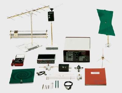
Satellite Training Kit
Our Satellite Communication Training Kit has built in antenna system which operates in the microwave frequency range of 5.8GHz & 2.4GHz. The trainer provides a wide range of Baud rates / Microwave modulation rates in a PC to PC link. The Satellite Communication Training Kit is also used for the study of the following parameters:
- Receiver and Satellite Emulator.
- Variable path loss at uplink and downlink channels.
- Measurement and Analysis of Carrier to Noise Ratio and Signal to Noise Ratio to examine the quality of signal.
- High RF output power and low noise.
- Built in Interference Generator and Noise Figure Analyser.
- Condenser microphone and speaker are provided for audio link.
- Display of PLL synthesized frequency in Transmitter.
- Camera and Video monitor for video link.
- Transponder for up-link and down-link.
- Dish X 2 & Patch X 2 for linear & circular polarization study for Helix antennas for 2.4 & 5.8GHz.
- Signal monitoring outputs at uplink & downlink.
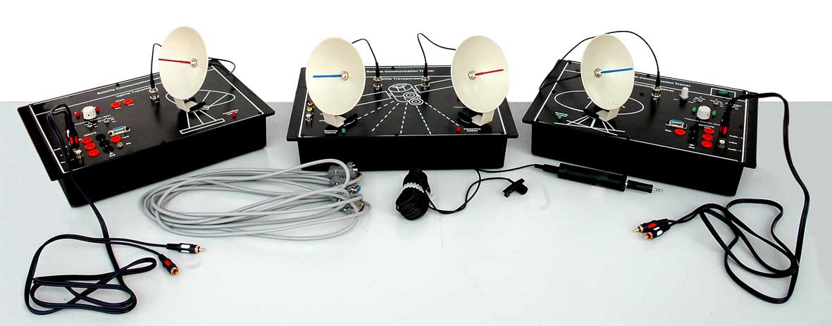
Satellite Communication Training Kit
Satellite Communication Training Kit
The basic components of a satellite system are its antennas which consists of repeaters and receivers also known as transponders. When we transmit a signal from earth to the satellite it refers to up-link and when a signal is received on earth from the satellite it is called down-link. The uplink frequencies are in the range of 5.9 Ghz to 6.4 Ghz and the down link frequencies are in the range of 3.7 Ghz to 4.2 Ghz.
These frequencies are used for Transmission from the satellite to the earth station. The uplink frequencies are converted to lower frequencies by the mixer and local Oscillator, the communication satellite acts as a repeater station as it receives the signal, amplifies it and then transmits over next frequency to avoid interference between the uplink signal and down link signal this is how a two way communication is established with the help of a transponder. Communication satellites can have multiple transponders. Transponders per satellite have increased rapidly over years since inception so as to increase the capacity of satellites because earlier a satellite with 2 transponder used to support a signal T.V channel or 240 telephone lines, Similarly a satellite with 48 transponder can accommodate 4000 Telephone Phone lines and 2 T.V channels. Today’s new generation satellites which use digital multiplexing technology can handle 120,000 Telephone lines and more than 500 T.V channels.
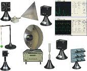
Satellite Training Kit
Product Code:AL-E507
SCOPE OF LEARNING:
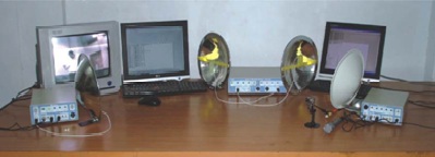
The basic components of a satellite system are its antennas which consists of repeaters and receivers also known as transponders. When we transmit a signal from earth to the satellite it refers to up-link and when a signal is received on earth from the satellite it is called down-link. The uplink frequencies are in the range of 5.9 Ghz to 6.4 Ghz and the down link frequencies are in the range of 3.7 Ghz to 4.2 Ghz. These frequencies are used for Transmission from the satellite to the earth station. The uplink frequencies are converted to lower frequencies by the mixer and local Oscillator, the communication satellite acts as a repeater station as it receives the signal, amplifies it and then transmits over next frequency to avoid interference between the uplink signal and down link signal this is how a two way communication is established with the help of a transponder. Communication satellites can have multiple transponders. Transponders per satellite have increased rapidly over years since inception so as to increase the capacity of satellites because earlier a satellite with 2 transponder used to support a signal T.V channel or 240 telephone lines, Similarly a satellite with 48 transponder can accommodate 4000 Telephone Phone lines and 2 T.V channels. Today’s new generation satellites which use digital multiplexing technology can handle 120,000 Telephone lines and more than 500 T.V channels. The Satellite Communication Lab provides an in-depth look at Satellite Communication Techniques and Concepts. It consists of Satellite Uplink Transmitter, Satellite Transponder Link and Satellite Downlink Receiver, which can be conveniently placed in the laboratory for experimentation. The Satellite Transponder Link also called as Satellite Emulator can also be placed at an elevated position if needed. The satellite transponder receives signals from uplink transmitter and retransmits at different frequencies to a downlink receiver. The uplink frequencies are selectable and can carry three signals video/data, audio/voice/tone (A1) and audio/voice/tone (A2) simultaneously. Any broadband signal or digital / analog data or square wave from function generator can be transmitted through this satellite link. A large number of experiments can easily be conducted. PC to PC Communication Link can also be established & studied.
Pulse Transformer on Board:
Features:
• High frequency S – band microwave operation in ‘License Free’ ISM Band
• High RF Output Power and Low Noise / Leakage
• PLL synthesized Frequency in Transmitter, Receiver and Satellite Emulator
• Choice of different selectable Transmitting & Receiving Frequencies with LED Indication
• Simultaneous Communication upto three different Signals possible
• Communicates Audio, Video, Digital / Analog Data, Tone, Voice, Function Generator Signals & PC (via RS232)
• Inbuilt Variable Audio Tone Generator (100 Hz to 1KHz)
• Study of S/N (Signal to Noise) & C/N (Carrier to Noise) ratios
• Emulation of Path Loss, Noise and Fading
• Signal Propagation Delay & Link Fail Operation
• Microphone and speaker provided for audio link
• CCD Camera and Video Monitor provided for Video Link
• 4 Detachable Dish Antennas with Shielded Cables for RF Signal
• Facility to attach Analog / Digital Communication Kits
• Detailed Instruction Manual with complete experiments
TECHNICAL SPECIFICATIONS:
Satellite Transmitter (Uplink)
2.411, 2.431, 2.451 & 2.471 GHz (Selectable & PLL Controlled) with Indicator
Satellite Emulator (Transponder Link)
Transponder with Selectable frequency Conversion Emulation of Path Loss, Noise and Fading
Signal Propagation Delay & Link Fail Operation
Transponder Receiver (Uplink)
Frequency : 2.411, 2.431, 2.451 & 2.471 GHz (Selectable & PLL Controlled) with Indicator
Transponder Transmitter (Downlink)
Frequency : 2.411, 2.431, 2.451 & 2.471 GHz (Selectable & PLL Controlled) with Indicator
Satellite Receiver (Downlink)
Frequency : 2.411, 2.431, 2.451 & 2.471 GHz (Selectable & PLL Controlled) with Indicator
Antennas
1. Parabolic detachable dish antenna with Teflon Cables for RF Signal & mount - 4 Nos
Accessories
2. Microphone
3. CCD Camera
4. LCD Monitor
5. BNC to RCA plug (for A/V connection) cables - 6 Nos.
6. BNC to BNC Cable – 2 nos.
7. RS-232 Cable – 2 nos.